 Tweet
Tweet
Front wing design case study: Mercedes W03
John Beamer takes a look at current trends in front wing design in F1 using the Mercedes W03.
Since the introduction of the 2009 technical rules, which closed off several areas for aerodynamic development, front wings have become one of the most important areas of car development.
This is because there are few other areas where designers have much freedom. Later rule changes have further limited the scope for improvements to the diffusers.
The front wing is a vital component because it is where the passing air first meets the car. The entire aerodynamic performance of an F1 car can be changed by the subtlest of alterations in front wing design.
The 2009 front wing

Cast your mind back to late 2008 when BMW ran the first 2009-specification car in an end of season test (see illustration above).
This one one of the first examples of post-2009 front wing design we saw. It was simple and boxy, with very square endplates which had the single function of pushing air around the front tyres.
The wing itself was a simple three-element device with none of the cascades or appendages we are now familiar with. (The 2009 rules also allowed it to be adjusted while the car was moving, but this rule was scrapped at the end of 2010).
Other teams followed with more refined concepts. Designers quickly realised a lot of lap time was available from a properly developed front wing. Outside of the FIA-mandated horizontal section below the nose there are comparatively few restrictions on what they can build.
This has resulted in an aerodynamic arms race that saw even midfield teams bringing updated front wings to every race.
The modern front wing – Mercedes W03

Fast-forward to the start of the 2012 season. This illustration shows the launch-spec front wing on the Mercedes W03.
Like the original BMW wing it has three element, but the similarities pretty much end there. It doesn’t take a trained eye to see how much more complex wing design has become in the space of just over three years.
The endplate structure is very intricate. It consists of multiple fins, some of which blend into the front wing elements.
There are a complex series of stacked cascades around the outer part of the wing. And there are further ‘indents’ across the leading edge and under-surface of the main plane. The Mercedes’ nose is thin, rounded and raised.
The modern philosophy of front wing design is that the device itself isn’t necessarily to create a ton of downforce but rather to condition the flow over the rest of the car. By manipulating how air leaves the front wing the flow to the tea-tray, sidepods, floor and diffuser can be optimised.
Nearly all teams use a three-element design such as this. Although a two-element design gives greater peak downforce, airflow separation on the underside of the elements is more of a problem and this compromises airflow to the rest of the car.

The second illustration shows the aerodynamic elements aft of the front wing (but not the suspension) – the undernose vanes, bargeboard and detail around the leading edge of the floor.
From this angle you can start to appreciate why the front wing needs to be so detailed to create the right flow environment for the rest of the car to work.

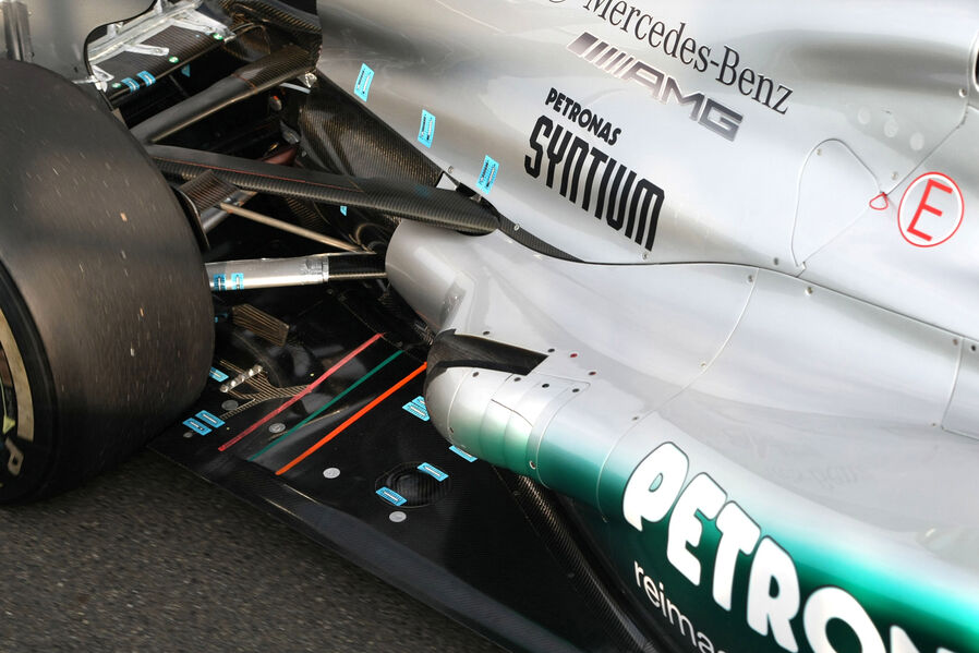
Add in the suspension arms, steering rack and brake ducts and the picture is even more complicated as shown in the third illustration.
Brake ducts are also relatively free from regulation and is a hotbed of development. The W03 brake duct has a simple aerofoil below the duct.
Don’t be surprised to see this area developed further as the car mature. The suspension arms are also faired for aerodynamic benefit and manage flow around the sidepods. However the steep angle of the wishbones means the effect is small.

The final illustration selectively indicates airflow streams generated by the front wing.
This is a not a complete picture, but it gives an idea of how various vortices are created. The inner cascade is a perfect example: the air above the cascade is at a higher pressure than the air below it.
This higher pressure air will ‘roll’ towards the low pressure zone to equalize this lateral pressure gradient, and it is this rolling motion that creates a vortex.
Vortices are useful because they can be directed with reasonable precision and they also create a sealing effect. The semi-circular footplate and other indents on the main plane underwing are all designed to capture and direct vortices.
For example, air above the footplate is at a higher pressure than that below. Air will roll over the side of the footplate and is capture by the semi-circular channel sealing the rest of the main plane.
The front wing of 2014
There is no doubt that F1 teams have and will continue to invest a lot of aero resource in front wing development.
The FIA has consistently shown it is prepared to close down development avenues it perceives as not beneficial to the sport or the commercial automotive industry.
Don’t be surprised if come the next aero regulations overhaul in 2014 will see the ability to develop the front wing severely curtailed – we already know they’re going to be narrower.
John Beamer takes a look at current trends in front wing design in F1 using the Mercedes W03.
Since the introduction of the 2009 technical rules, which closed off several areas for aerodynamic development, front wings have become one of the most important areas of car development.
This is because there are few other areas where designers have much freedom. Later rule changes have further limited the scope for improvements to the diffusers.
The front wing is a vital component because it is where the passing air first meets the car. The entire aerodynamic performance of an F1 car can be changed by the subtlest of alterations in front wing design.
The 2009 front wing
Cast your mind back to late 2008 when BMW ran the first 2009-specification car in an end of season test (see illustration above).
This one one of the first examples of post-2009 front wing design we saw. It was simple and boxy, with very square endplates which had the single function of pushing air around the front tyres.
The wing itself was a simple three-element device with none of the cascades or appendages we are now familiar with. (The 2009 rules also allowed it to be adjusted while the car was moving, but this rule was scrapped at the end of 2010).
Other teams followed with more refined concepts. Designers quickly realised a lot of lap time was available from a properly developed front wing. Outside of the FIA-mandated horizontal section below the nose there are comparatively few restrictions on what they can build.
This has resulted in an aerodynamic arms race that saw even midfield teams bringing updated front wings to every race.
The modern front wing – Mercedes W03
Fast-forward to the start of the 2012 season. This illustration shows the launch-spec front wing on the Mercedes W03.
Like the original BMW wing it has three element, but the similarities pretty much end there. It doesn’t take a trained eye to see how much more complex wing design has become in the space of just over three years.
The endplate structure is very intricate. It consists of multiple fins, some of which blend into the front wing elements.
There are a complex series of stacked cascades around the outer part of the wing. And there are further ‘indents’ across the leading edge and under-surface of the main plane. The Mercedes’ nose is thin, rounded and raised.
The modern philosophy of front wing design is that the device itself isn’t necessarily to create a ton of downforce but rather to condition the flow over the rest of the car. By manipulating how air leaves the front wing the flow to the tea-tray, sidepods, floor and diffuser can be optimised.
Nearly all teams use a three-element design such as this. Although a two-element design gives greater peak downforce, airflow separation on the underside of the elements is more of a problem and this compromises airflow to the rest of the car.
The second illustration shows the aerodynamic elements aft of the front wing (but not the suspension) – the undernose vanes, bargeboard and detail around the leading edge of the floor.
From this angle you can start to appreciate why the front wing needs to be so detailed to create the right flow environment for the rest of the car to work.
Add in the suspension arms, steering rack and brake ducts and the picture is even more complicated as shown in the third illustration.
Brake ducts are also relatively free from regulation and is a hotbed of development. The W03 brake duct has a simple aerofoil below the duct.
Don’t be surprised to see this area developed further as the car mature. The suspension arms are also faired for aerodynamic benefit and manage flow around the sidepods. However the steep angle of the wishbones means the effect is small.
The final illustration selectively indicates airflow streams generated by the front wing.
This is a not a complete picture, but it gives an idea of how various vortices are created. The inner cascade is a perfect example: the air above the cascade is at a higher pressure than the air below it.
This higher pressure air will ‘roll’ towards the low pressure zone to equalize this lateral pressure gradient, and it is this rolling motion that creates a vortex.
Vortices are useful because they can be directed with reasonable precision and they also create a sealing effect. The semi-circular footplate and other indents on the main plane underwing are all designed to capture and direct vortices.
For example, air above the footplate is at a higher pressure than that below. Air will roll over the side of the footplate and is capture by the semi-circular channel sealing the rest of the main plane.
The front wing of 2014
There is no doubt that F1 teams have and will continue to invest a lot of aero resource in front wing development.
The FIA has consistently shown it is prepared to close down development avenues it perceives as not beneficial to the sport or the commercial automotive industry.
Don’t be surprised if come the next aero regulations overhaul in 2014 will see the ability to develop the front wing severely curtailed – we already know they’re going to be narrower.


Comment